With a PDF of the factory service manual onhand, it is straightforward to remove the door panels & unbolt the existing mirror assemblies. Here is the Outback with that cool shaved look!
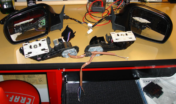
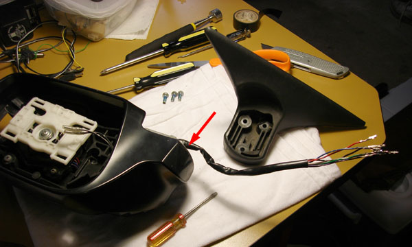
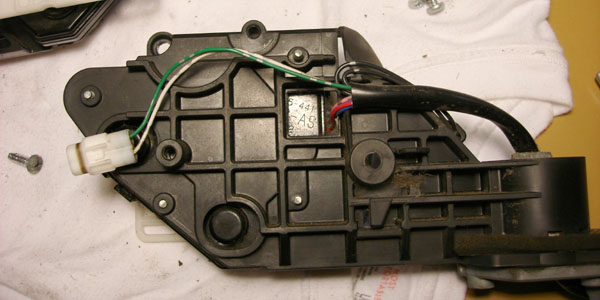
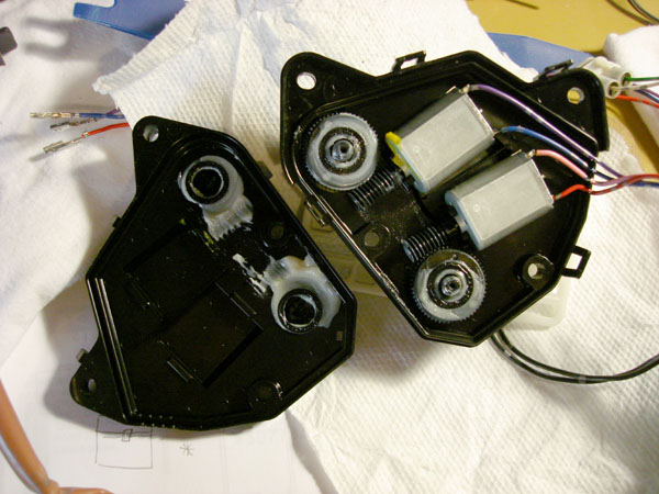
Here are my OEM mirror assemblies together with the JDM power-fold frames. These frames have a circuit board including a relay to cut power to the motor anytime it stalls, which is normally when it has fully opened or closed, but it would also protect the motor from burnout if it becomes jammed or frozen.
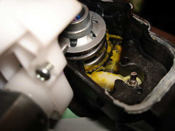
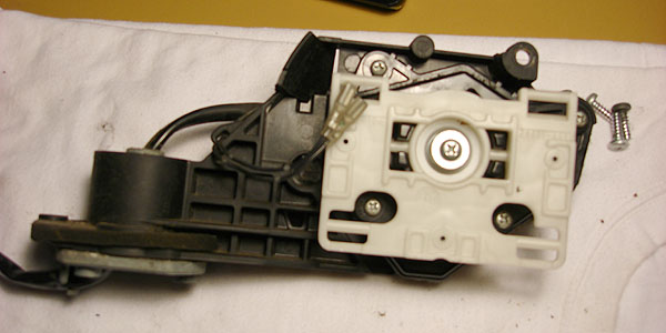
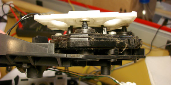
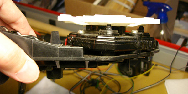
With the protective cap off the mechanism, I tore it down even further to see what was in there.
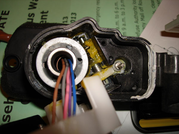
The vertically oriented motor drives a worm gear, which reduces through another worm to achieve the folding.
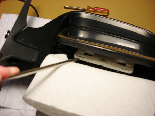
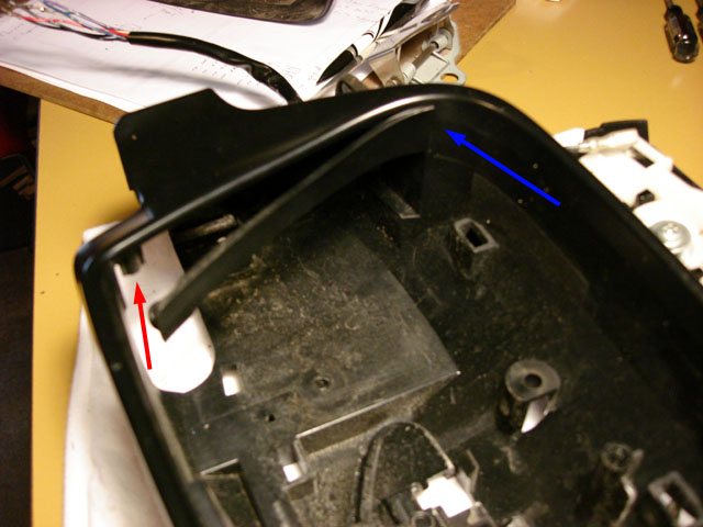
With the glass adjusted fully up there are 2 spots where you can gently pry with a flat screwdriver to detach 2 lower clips from the white plastic plate. I padded the edge of the mirror body with a couple layers of paper towel.
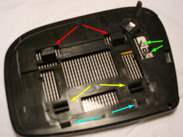
You then adjust the mirror partially down so you can orient the glass & separate 2 upper catches from the white plastic plate. Red = upper catches, yellow = lower clips, blue = markings showing where to locate a screwdriver for prying, & green = terminals for heated glass; be gentle detaching those.
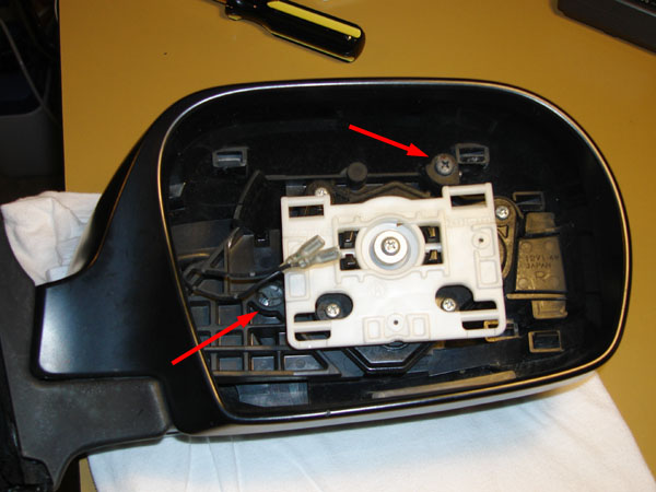
Here's the mirror body with glass removed. 2 of the 5 screws that attach the mirror body to the frame are called out here.
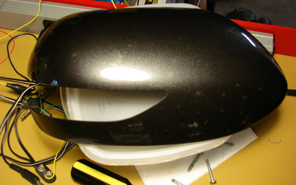
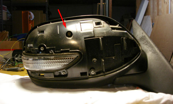
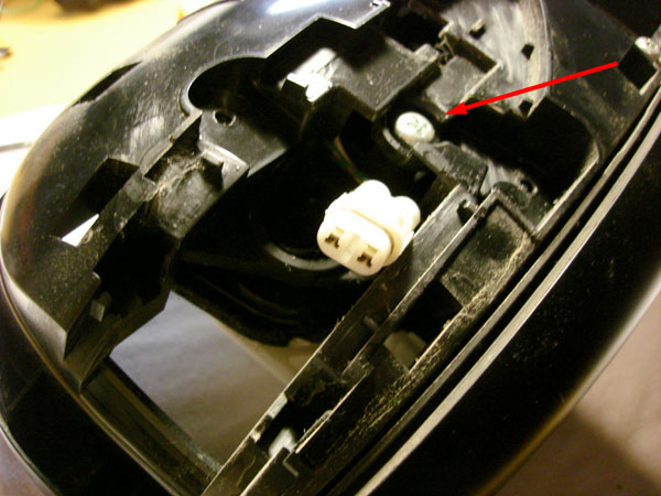
Next, the mirror scalp cap is removed. On mirrors with turn signals, the cap is snapped in place with 6 locking tabs. The 4 tabs indicated by green arrows are easy to reach & release with your fingers.
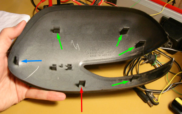
Even the factory service manual basically instructs you to release the easy tabs then pull the cap forward until the remaining tabs release, but cautions to not remove forcibly or you will break the tabs, lol. Not sure how that is possible. I ended up removing the 4 screws that hold the glass adjust motor assembly to the frame, so I could move that motor assembly aside & reach a long flat screwdriver through a hole in the frame & carefully press on the tab indicated by the red arrow.
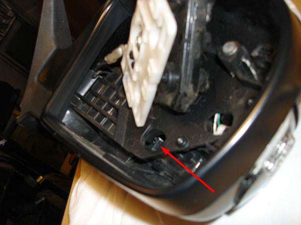
Now the only tab still holding is the one indicated by the blue arrow, & you can wiggle the scalp cap carefully until that tab releases.
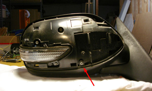
The mirror body now looks like this. 2 more of the 5 screws that attach the mirror body to the frame are on the front side. 1 is shown here & the other is behind the turn signal.
The LED turn signal repeater can be separated after removing 2 screws...
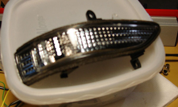
...& unplugging a small connector. Body-to-frame screw 4 of 5 is shown here.
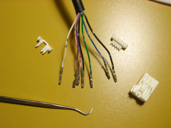
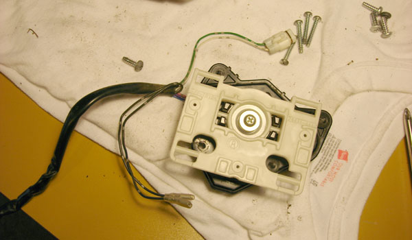
It's about time to separate the mirror frame from the base. The connector must be de-pinned since it is too big to pull through the base. Even if you have the factory wiring diagrams, make your own notes of which wires go to which slots on the connector.
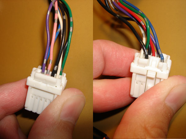
It seems that Subaru used connectors with 6, 8, or 10 positions depending on the various options present in a mirror. A set of dentist style picks was ideal to reach in & release the internal plastic lock tab for each wire.
My mounting base had an oblong rubber gasket that fit over 2 of the bosses with a sleeve in the middle for passing the wire loom through, & into the car. I had to remove some adhesive foam to be able to pull the gasket off the loom.
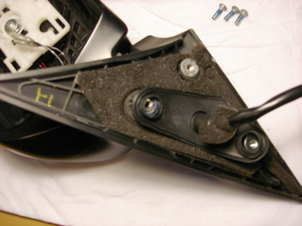
I had to cut the foam gasket a bit & fold it back to reveal a retaining spring clip. With needle nose pliers I was able to flex that clip enough to lift it off the peg. When I repeated on the other mirror, that clip broke, & it seems OK without it as long as you don't pull hard on the loom from inside the car.
The base is attached to the mirror with 3 screws that are thread locked from the factory. Use a big philips screwdriver that fits tight, press very hard, & turn slowly. You don't want to strip these. With those 3 screws removed, you can feed the loom through the base & separate it from the mirror. The last of 5 screws holding the mirror body to the frame is indicated but not shown.
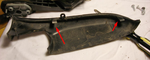
The lower part of the mirror cap is held on by a screw up front...
...& tabs that are released from inside the mirror body. The tab on the right (further away from the car) is easy to reach, but the left/inner tab required me to unbolt the mirror body from the frame (the 5 screws illustrated above) to allow enough wiggle room to reach it.
Only the passenger side mirror on my car has this plastic spacer strip, held in place with a tab (blue arrow) & 1 screw (red arrow). On a RHD car, you'll find a similar spacer on the left side mirror.
Here is the frame with the body completely removed.
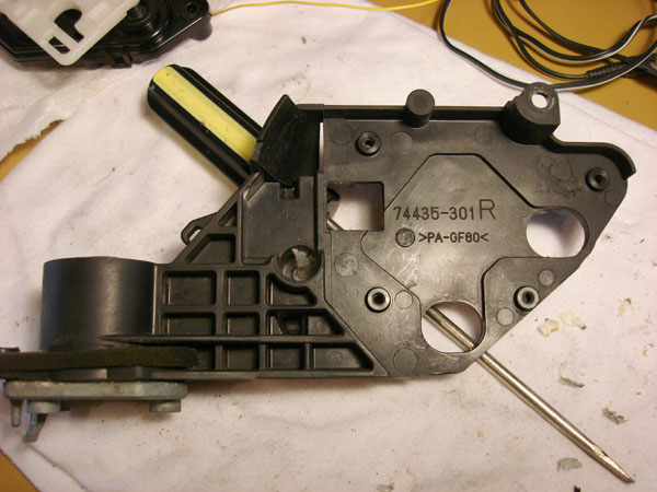
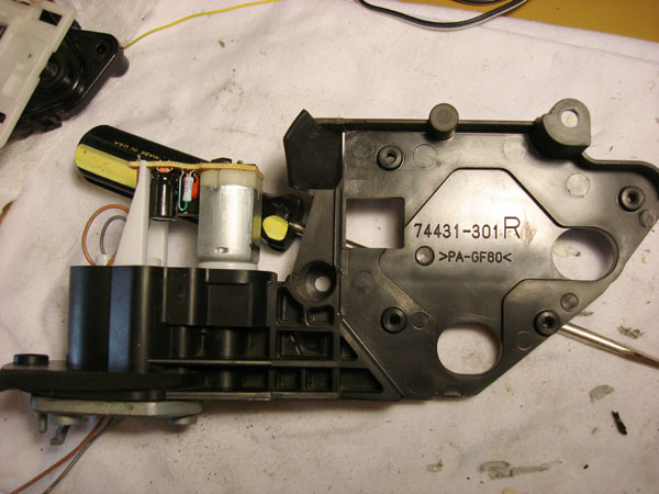
There are a surprising number of design variations between mirrors destined for LHD vs RHD markets. Looking at the right side mirror on my USDM LHD car, the mounting legs that connect my original glass-adjust motor to the frame are biased for a driver seated on the opposite side of the car.
Conversely, the glass-adjust motor from the right side of the RHD drive donor car is more angled for a driver sitting right beside it. The left side mirrors from a LHD vs RHD car are correspondingly different.
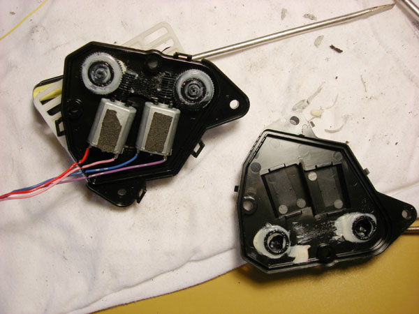
I think there would be adequate adjustment range with either glass-adjust motor assembly, but I chose to swap them while I had the chance. Here are the bare frames.
Here's my US glass adjust motor, heat wires & turn signal wires, all fed through the loom. This loom will need to pass down through the fold motor's protective cap, which is a route about 2 inches longer than original, which will later require an adjustment to its connector behind the door panel.
Since the top & bottom cases of the glass-adjust motor assembly are angled differently to be market specific, I considered swapping the JDM internal motors (which are identical except for longer wires & a thin strip of adhesive foam padding) into my USDM case
The heat & turn signal wires would still be shorter, so I left it alone.
Reassembling the protective cap over the fold motor & routing the wiring turned out to be a PITA. I wanted to reuse my existing black loom for the additional protection from water & abrasion, but that meant I had to feed it through the cap- with the cap still separated from the motor body- & then determine a way to let the tan & gray fold motor wires join it, so it could finally be fed down through mounting bases & into the door. I ended up cutting out of a sliver of the loom...
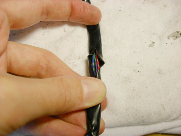
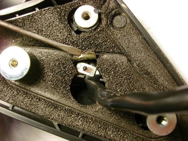
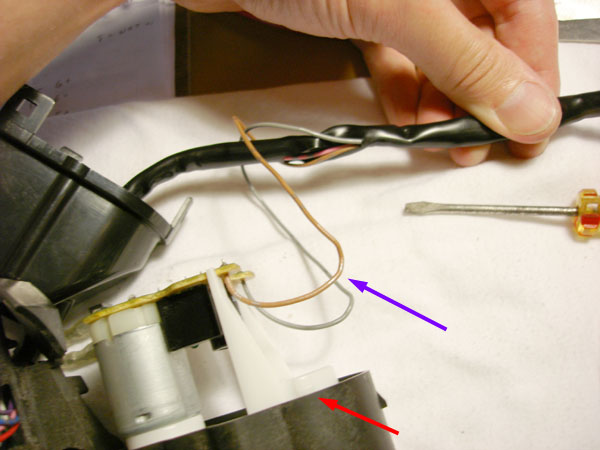
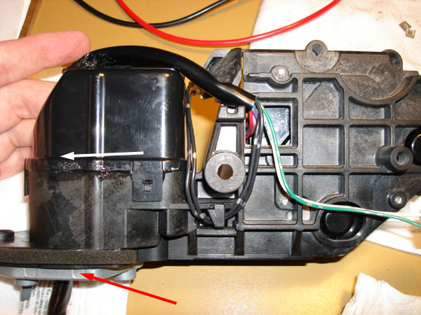
...so I could fish the tan & gray wires through in the direction towards the car. Those wires head from the circuit board down around a catch (red arrow) in the white nylon (purple arrow is the vicinity where the wire bends around the catch). The wires head back up, loop over again, & feed down into the loom. This closely matches the factory routing of these 2 wires to allow plenty of slack as the mirror folds. I actually cut out a rectangular section of the loom, not just a slit, so the wires wouldn't be abraded as they fold. I let that opening face towards the fold motor.
Reassembly was a bit tricky. I needed to replace the sealant where the protective cap snaps on to the body & all I had was some black silicone. I had to daub it in place with a toothpick. As I was lowering the cap I was also gently positioning & pulling the wire loom out the bottom. With the cap snapped on, I positioned the loom snugly as shown & applied a gob of sealant where the loom enters the cap, to help prevent any water dripping down inside. Basically, the loom is stationary at the red arrow & twists in the vicinity of the white arrow when the mirror folds. Note the different routing of the heated glass wires.
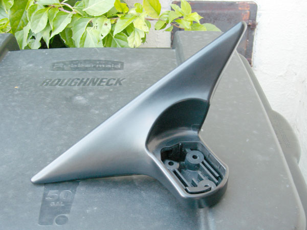
With everything torn apart, I took the opportunity to re-black the mounting bases. Despite being relatively young they were already faded & rough looking. After reading tons of user testimonials on various products advertised to darken & restore bumpers & other faded exterior trim, I went with Forever Black Bumper & Trim
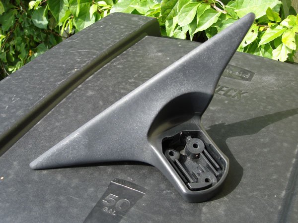
I meticulously cleaned & prepped the pieces & applied 5-6 thin coats, allowing a thorough dry between each coat. I used a basic foam paint brush instead of the applicator that comes on the bottle. They look better than new. The car has already experienced a few days of rain & there is no sign of any streaking or fading or runoff. [Update- these have been on the car for over 2 months now, enduring plenty of rain & varying weather, & they still look great. I suspect the thorough cleaning & prepping was the bigger part of my good experience. There are other exposed parts of the car- the roof rack rails & crossbars, the cowl panel at the base of the windshield- that are candidates for cleaning & re-blacking, but the prep & application will be more challenging on items attached to the car.]
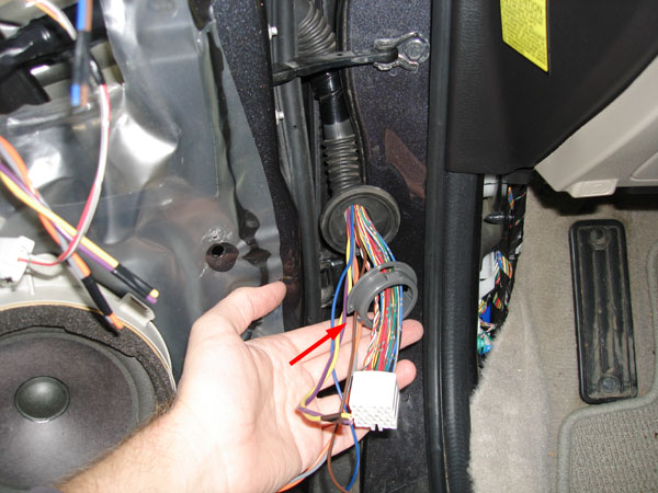
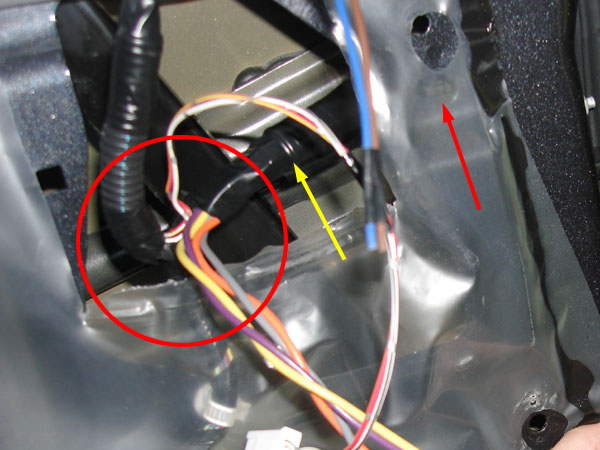
Reassembly of the entire mirror is involved but straightforward. It is basically a reverse of disassembly. Routing the loom down through the base seems like you are bending the wires too much, but there is only 1 way to do it & there's a peg to guide it. I did not apply threadlock when reattaching the mirror to the base, I just tightened firmly but carefully to prevent stripping. Once you pull the loom & wires back through the base, & reapply that rubber gasket, you can reinsert the pins into the connector. My mirror attaches to the sail panel with 3 bolts, one of which has a cover plug that's easy to forget to put back. I had to separate the socket (white arrow) from its original hold-down clip (yellow arrow) to free up some slack to reach the mirror plug, since it is now ~2" shorter. I applied a small piece of adhesive weatherstrip foam to the socket so it won't rattle against the door. Since the black adhesive makes it impossible to cleanly remove the vapor barrier, I just cut an access patch which I later closed up with duct tape. You can see the mirror fold wires hanging free, & the blue & brown wires I ran through the door to connect to them. I was unable to source that connector with additional slots, so I just inserted ~4mm of stripped wire into the female ends of the fold wires & taped it good for now.
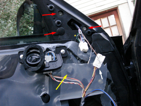
I had to do some untaping & re-taping in the vicinity of the red circle to free up additional slack in the loom heading vertical to the mirror connector. I also had to untape & re-tape that short piece of loom so I could add the 2 new wires for the fold motors. The entire door harness enters the door through a rubber sleeve that is folded over & taped tight where the wires exit (yellow arrow) & also held down with a zip-tie clip (red arrow), so I had to pop that clip out, use a pick to open up the zip, & untape/unfold so I could fish the added wires through.
With the floor trim removed, the large square door connector can be separated. The rigid gray plastic ring must be pried away from the body & then the connector can be pulled through. The entire rubber sleeve & door bellows can then be pulled into the door & out through the opening made in the vapor barrier (separate the ring from the rubber bellows to help maneuver everything) which finally lets you stretch the sleeve straight so you can fish wires. That ring is notched (red arrow) so the round rubber cover will only fit in one orientation for reassembly. Since the wire pulling was such a PITA I chose to pre-install 2 pairs of wires for a future stereo upgrade that will drive a replacement mid-range & tweeter discretely.